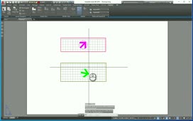
How many times have you opened up a drawing file and looked at the scale and it was not the same as the viewport? In this quick tutorial we are going to take fields a step further and link to a viewport, adding a formula to modify the scale bar. We are going to open up a drawing and create a viewport and set the viewport scale to 1=10 in decimal units and a custom scale name of 1”=10’. Within our drawing we also have a typical scale bar as shown in Figure 1. This scale bar can be a block with attribute values or just an object within AutoCAD containing text. Notice the grayed out areas on the bar, these areas are going to be the fields that we will link to our viewport starting off with the 1″=10′ field as shown below.
Figure 1: Typical Scale bar with Fields shown.
Start by moving to the text area after the SCALE (i.e. 1″-10′). Right click the text and select insert field on the menu. This will bring up the field menu in AutoCAD. Under the field category select objects as shown below then click the object type button. You will now be prompted to pick an object. Pick your viewport that you have within your current drawing.
Figure 2: The Object Field Category
Next, AutoCAD will bring up another menu indicating that the object is a Viewport. Select custom scale then use the scale name as shown in Figure 3 below and change the value to Use scale name as shown.
Figure 3: Custom Scale property
We now have the correct scale name shown below the bar as shown in Figure 1. Experiment by changing the viewport scale within your drawing and and watch this value change as the viewport changes. Next we have to make sure the numbers on the top portion of our block correspond with the scale we have selected. Right-click the first number (i.e. number 10 – Figure 1) on the scale bar and hit insert field. Again, using the same technique as before but adding a few new steps as shown in Figure 4. In step 4 we will highlight the text in the field expression – right click and copy and hold.
Figure 4: Field category names and data
Under the field category section move to the formula selection under field names as shown in Figure 5. We are now going to follow the steps as shown below. In Figure 5 select Formula. Next in the window shown in step 2 paste the formula which you copied from the previous section. One thing we need to do here is in front of the gyred out section type 1/ (i.e. one divided by). You need to add this part to the formula in order for AutoCAD to calculate the scale. Remember we are using the value #:1 (Step 3 – Figure 4) which means we will have to divide that by one to retrieve the whole number. Finally in Step 3 below change the precision back to 0 for a clean scale. Your precision can be important for the scale value to be exact, explore using options within this field.
Figure 5: Using the formula category
To get the final part of the scale bar (the number 20 in our example) simply copy your field (the number 10 in the scale bar) over to the section where you want the number doubled (in this example 20). Add the multiply by 2 after your formula as shown in Figure 6 and your value will be double what the first selection was, in this example 20.
Figure 6: Multiple the value of the viewport scale by 2.
With a little manipulation you can use architectural, scientific, and engineering units to receive the same results. Look at the number and perform the necessary calculations to get accurate results.Your final scale bar will have fields as shown in Figure 7. This scale bar can be used in a template where it is linked to the viewport within the template file. If you plan to use it on a current drawing you will need to follow the steps selecting the viewport and changing the formula for that object.
Figure 7: Final scale bar linked to Viewport.
Your final scale bar will have fields as shown in Figure 7. This scale bar can be used in a template where it is linked to the viewport within the template file. If you plan to use it on a current drawing you will need to follow the steps selecting the viewport and changing the formula for that object. You have to keep this bar linked to a viewport otherwise the numbers will be invalid and you will end up with a ### as a result linking the text object to nothing.
Source: Autodesk


