This article was updated on October 26, 2018 to reflect the recent enhancements and bug fixes made to this feature.
AutoCAD-based products can import data directly from PDF files into your drawing files, but are there any practical limitations to know about?
The answer depends on your intended use.
For example, if you’re simply importing catalog items, a schedule, or a landscape plan for visual reference, the answer is No, there are no practical limitations. You can stop reading right here. Enjoy the rest of your day.
On the other hand, if you require higher precision, plan to use object snaps and offsets, and will be duplicating objects imported from PDFs, you need to understand the limitations intrinsic to the imported data.
Let’s compare the differences in the data stored in a PDF with the data stored in a DWG™ file, and see how that affects your results.

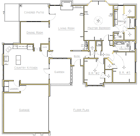
Floor plan imported from a PDF
Contents
Comparing PDF and DWG Formats
There’s a profound difference between PDF and DWG files in data content, format, and structure.
The data in PDF format supports the following:
- Real numbers that are usually represented with single-precision floating-point accuracy in recent versions
- Five graphical object types: path (line segments and Bézier curves), shading, TrueType™ text, inline image, and external
- Several properties that include primarily colors, layers, and line widths
In contrast, the data in AutoCAD DWG format supports a far richer data set including the following:
- Real numbers that are represented with double-precision floating-point accuracy, which is several orders of magnitude more precise than single precision
- More than 60 types of geometric objects, including compound objects such as dimensions, hatches, and blocks
- More than 50 types of properties
- Object associativity such as is available with hatches, blocks, and dimensions
Due to the difference in precision between PDF and DWG formats, the values for coordinates, angles, distances, and widths are rounded off in PDF format. As a result, objects will be modified slightly when you output geometric data to a PDF file. These differences are most noticeable when working with large distances and dynamic ranges, as is common with large maps.
Note: The accuracy that’s lost is difficult to restore without employing inferences. More about inferences later.
Behavioral losses when converting a drawing to PDF include the following:
- Block references become geometric objects as if exploded
- By default, non-continuous linetypes become separate collinear objects
- Hatch patterns become many individual objects without associativity
- Dimensions become individual lines, 2d solids, and mtext objects
- TrueType text will maintain its fidelity when the same fonts are available on your computer
- PDF files generated from AutoCAD drawings store SHX-font text as geometric objects
TrueType Fonts
PDF automatically includes Courier-, Helvetica-, Times-, Symbol, and ZapfDingbats fonts. It will also use any TrueType fonts available on your computer, or it will use a substitute font with similar parameters.
Converting Data To and From PDF
To convert data to and from PDF requires direct translators that interpret and try to reconcile the data. These direct translators are included in each AutoCAD product and are usually called “drivers” depending on the context.
Note: PDF drivers, which are the responsibility of each company that uses them, can vary in capability and quality. These differences will affect PDF import or export operations between products. For example, dpi (dots-per-inch) output resolution can be set to different values in some products. In AutoCAD, you can specify a maximum of 4800 dpi.
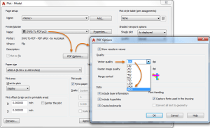
Changing the vector output quality
Using a lower output resolution decreases the PDF file size but increases the round-off errors.
Understanding the Role of Inference
After the PDF data is imported, the biggest challenge is inference. This is a process by which AutoCAD starts with the equivalent of exploded data (what we affectionately call “grass clippings”) and makes some best guesses to reconstruct more precise locations, object types, and associations.
For example, AutoCAD must deal with questions such as the following:
- Is this line supposed to be exactly horizontal?
- Should the length of this line be rounded to exactly 10.00000000?
- Should these two endpoints be made coincident?
- Should these four arc-shaped objects be combined into a circle, or are they closer to an ellipse or a closed spline?
- Are these objects part of a block?
- Are these objects part of a hatch object?
- Are these collinear line segments part of a non-continuous linetype?
- Is this geometry and text supposed to be an associative dimension object?
- Is this geometry a text object that was created with an SHX font?
- And so on . . .
Currently, AutoCAD supports the following inferences:
- Circles are inferred from objects that closely approximate a circle
- Ellipses are inferred if the elliptical geometry was represented in the PDF as a sequence of lines rather than Bézier curves
- B-splines are inferred from Bézier curves
- Polylines optionally are inferred from a contiguous series of lines and arcs
- Solid hatches optionally are inferred from filled areas in the PDF
- Lines with a dashed linetype optionally are inferred from a series of collinear lines that approximate a dashed line (this option is not always desirable)
Note: Text objects that originally used SHX fonts can be reconstructed with the PDFSHXTEXT command
The important concept? The inference process is imperfect and will often require cleanup.
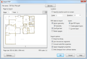
Options available in the Import PDF dialog box
Conclusion
When it comes to PDF to DWG conversion, it’s best to think of PDF as a form of electronic plot output that’s great for visual reference, embedded hyperlinks, and limited transfer of information between different functional groups and audiences.
Here are some tips:
- When you need to maintain precision, be careful about mixing data from different sources that do not maintain the same level of precision.
- Some PDFs are generated with the dpi output deliberately set low to provide only a visual representation with low precision.
- Similarly, some PDFs contain only a raster scan of a drawing. AutoCAD doesn’t support raster-to-vector conversion. Converting raster images to vector data with specialized software cannot provide the same level of precision as objects created directly with AutoCAD.
When you understand the underlying limitations inherent in PDF files, you can set reasonable expectations and get the maximum benefit from this valuable capability in AutoCAD.
Source: Autodesk


