Creating a 3D Mesh Sphere
The program provides a number of tools for creating mesh primitives. For example, the Mesh Sphere tool creates a 3D mesh sphere, with its latitudinal lines parallel to the XY-plane and its central axis parallel to the Z-axis of the current UCS. The number of tessellation divisions is controlled by the current Mesh Primitive Options.
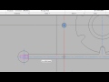
To start the command, on the Mesh ribbon, in the Primitives panel, expand the split button and click the Mesh Sphere tool. The program prompts you to specify the center point of the sphere, and the other options are almost identical to what you see when drawing a circle. For example, in addition to defining the size of the sphere as a center point and either a radius or diameter, or you can define it using three points, two points, or the tangent-tangent-radius option.
Click to specify the center point of the sphere. The program then prompts you for the radius, or you could choose the Diameter option. Specify a radius of 30 units and then press ENTER. As soon as you do, the mesh sphere is created.
Start the command again and then choose one of the other options. For example, right-click and choose 3P. Then, click to specify three points. As soon as you do, the sphere is created, since you have specified both its location and size.
After creating the mesh, you can use mesh modification tools to smooth, crease, split, and refine the mesh.
Source: Autodesk