
In this regard, how do I create a section mark in AutoCAD?
- On the default tool palette set, click the Design tab, and then click the Vertical Section tool.
- Specify the start point of the section line.
- Continue to specify points to define the section line, if needed.
- Specify the endpoint of the section line, and press Enter.
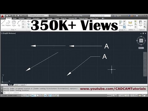
Quick Answer, how do you make an arrow in AutoCAD?
You asked, how do I draw a cut line in AutoCAD? On the Annotation tool palette, click the Cut Line Tool. In the drawing area, specify the point where you want the cut line to begin. Specify the point where you want the cut line to end. Specify the extents of the break.
Similarly, which way do section arrows point? Arrows are placed at the ends of the cutting plane line to indicate the direction of sight. The arrows point to the portion of the object that is kept.

Contents
How do you make a section line?
How do I add an arrow to a line in AutoCAD?

How do you draw a polyline arrow in AutoCAD?
- Start the polyline command and select a start point.
- Turn on ortho (F8) as you move your cursor and see how you can adjust the length of the arrow as shown in Figure 3.
- Hit Enter when you have your desired size and the polyline segment will end.
- Let’s try one more.
How do I change the arrow style in AutoCAD?
On the Format menu, click Dimension Style. In the Dimension Style Manager dialog box, click the Modify button of the current dimension style. On the Symbols and Arrows tab of the Override Current Style dialog box, select the size and leader type that is needed. Click OK to close each dialog box.
How do I trim and break a line in AutoCAD?
- Type in BREAK at the command line or select break tool.
- Select the object you wish to break.
- Select First Point Option (F) then.
- Pick the point where you wish divide the object.
- When prompted to specify second break point, type @ and Enter.
What are the section line symbols?
Section line symbols show the kind of material from which the part is to be constructed. The material may not be indicated symbolically if its exact specification is shown elsewhere on the drawing.
How do you divide a line into a segment in AutoCAD?
DIVIDE command: Select Divide tool from expanded Draw panel of Home tab, you can also use its command equivalent DIVIDE. Click on the spline and enter the number of segments in which you want to divide the spline, I will select 6 segments for our case. Press enter to exit the command.
What is Section AA in drawing?
The cutting plane is represented by a cutting plane line. The cutting plane line is defined as A-A, and the section view is defined as view A-A.
What is the difference between the section line and the Centre line?
Centre lines are drawn to indicate the exact centre of a component being drawn. They are made from a series of lighter long and short dashes. Section lines are special lines placed on a drawing which indicate the area of the drawing through which an imaginary cut has been made to reveal internal details.
What are the 7 types of section views?
There are a number of different types of sectional views that can be drawn. A few of the more common ones are: full sections, half sections, broken sections, rotated or revolved sections, removed sections, offset sections, and assembly sections.