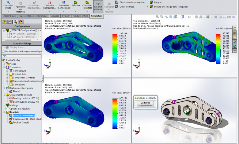
SolidWorks Simulation allows you to simulate your concept to detect potential failures and breakages in advance. When we get to this stage, it is common to change the material, thickness, add support, etc. How do you compare all these differences in one view?
First step: model part configurations
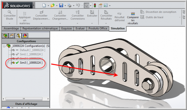
In order to use the comparison of the results with the configurations, it is obviously necessary to first have a configuration in our file. In the following example, we have 3 configurations with different cutouts in the part. One configuration with angled grooves, the other without grooves and finally another with four vertical grooves.
Second step: Create a simulation on the three configurations
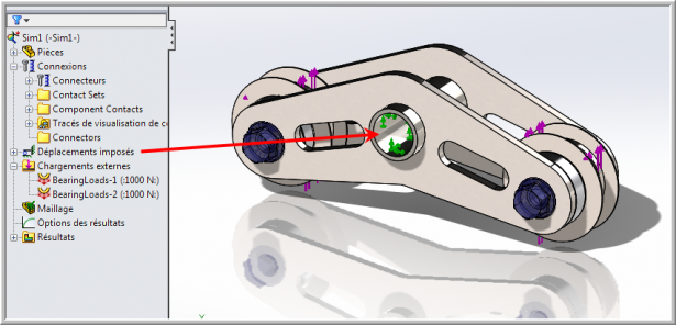
Then, you have to do a simulation on one of the configurations by adding forces, restraints, connectors, etc. In the following example we have the part attached to the center shaft with end bearings and bolt connectors that were added automatically with SolidWorks Toolbox. In order to compare the results, we must also do studies on the other configurations. In our example, the attributes are the same so it is possible to copy the studies to the other configurations.
Last step: Compare the results according to the configurations
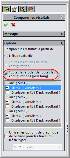
Finally, the last step is to use the “Compare results” function found in the Simulation tab:
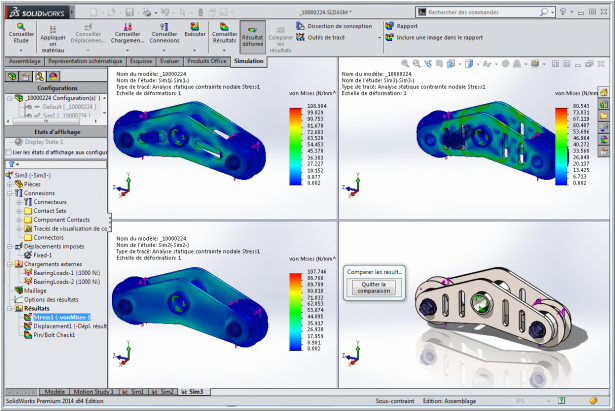
We will choose the option “All studies of all configurations” and we will choose the type of result we want to have on the screen. We have the option of having four results at a time. In our example we are going to choose only the stress results.
All you have to do is call your boss and show him the fruit of your labor on your screen. We can clearly see the difference in Stress depending on the type of cut in our room.
You can watch our Tech Brief on this topic or view several other tips on SolidWorks Simulation by clicking here.
