Contents
What is a cross section view?
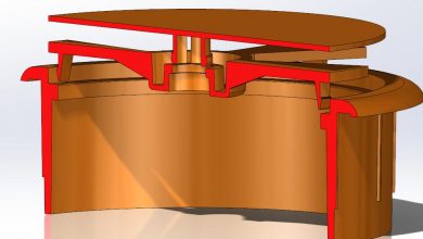
In technical drawing a cross-section, being a projection of an object onto a plane that intersects it, is a common tool used to depict the internal arrangement of a 3-dimensional object in two dimensions.
What is cross section plan?
A cross section, also simply called a section, represents a vertical plane cut through the object, in the same way as a floor plan is a horizontal section viewed from the top. … A sectional elevation is a combination of a cross section, with elevations of other parts of the building seen beyond the section plane.
How do you move a section arrow in Solidworks?
To edit the view arrow: On the view arrow, drag the center handle (to move it) or the end handle (to resize it). You can set an option to reuse the letters from a deleted view in a drawing without manually re-lettering the views.
What is an example of a cross section?
The definition of a cross section is a section of something that has been cut down the middle to show what is inside. An example of a cross section is what you see on the inside when you cut a layered sandwich in half.
What is cross section area?
The cross-sectional area is the area of a two-dimensional shape that is obtained when a three-dimensional object – such as a cylinder – is sliced perpendicular to some specified axis at a point. For example, the cross-section of a cylinder – when sliced parallel to its base – is a circle.
What is full section view?
What is full section? A sectional view obtained by assuming that the object is completely cut by a plane is called a full section or sectional view. Figure a shows the view from the right of the object shown in Fig. a, in full section. The view should also contain the visible parts behind the cutting plane.
What is a removed section view?
The removed section view is a zero-thickness slice through the model showing only cut edges and hatching perpendicular to the cutting line. That’s different than the traditional section view, which is projected parallel to the cutting line.
When and why is a section view necessary?
In which case, the direction of sight is towards one half of the object. The other half is then mentally discarded. Drafters use sectional views to improve the clarity of complex objects when internal surfaces result in too many hidden lines. Special conventions are used to make a sectional view easy to understand.
How do you move a section view in Inventor?
Select the method of the section view, projected or aligned, if possible. Move the preview to the appropriate location, and then click to place the view. (To place the view without alignment to the parent view, press Ctrl as you move and place the preview.)
How do you find the minimum cross-sectional area?
Try formula sq rt I squared x t divided by k and it gives you 1.88 so nearest cpc size is 2.5mm. So a minimum CSA of 2mm is required, 2.5mm is the correct answer.
What are the 7 types of sectional views?
There are a number of different types of sectional views that can be drawn. A few of the more common ones are: full sections, half sections, broken sections, rotated or revolved sections, removed sections, offset sections, and assembly sections.
What section that shows the quarter part removed from the view?
When the quarter of the object that was cut is removed, the remainder is called a “half section.” A half section view is effective only on symmetrical objects, and its main purpose is to show an object’s internal and external construction in the same drawing.
How do you read a station number?
Station numbers usually increase from the beginning of the project to the end of the project. Also, stationing usually runs from South to North or from West to East. The beginning station of a project is usually arbitrary. Generally, it will be 10+00 or 100+00.
How do you draw a plan view?
To start, you will draw a horizontal line with a point in the middle. After this, draw lines from the point where you want to draw the buildings in the picture. Then, draw boxes inside the lines that you drew out. Then, you will draw in vertical lines on the bottom of the page, which will act as the ground.
How do you show a section line in a plan?
In plan view, the section line is displayed as you would expect on a construction document. The section marks point in the direction that the section is cut. In an isometric view, the same section line is displayed with a boundary that defines the extents of the section.
