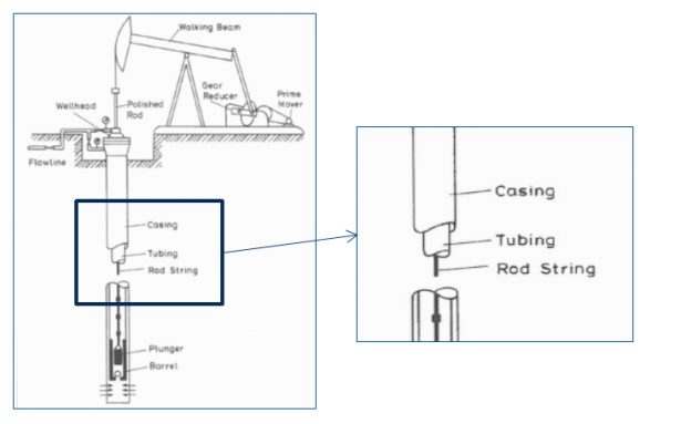
The design of oil and gas products presents many unique challenges. For designers and engineers, the first step is to understand how an oil well works and what it is made of. The figure below shows a typical oil well. The sheath of the well is in contact with the ground, it is therefore subjected to an external pressure. The role of the column is to convey the fluid, it can therefore be subjected to various stresses such as internal and external pressure as well as tension and compression forces.
The sucker rod is located inside the column and is used to activate the pump located at the bottom of the oil well. A typical oil well is between 1,500 m and 5,000 m deep, depending on the area of exploration. Many connections are bundled into a single cable, so if just one of those connections fails, the entire output of the oil well is affected.
Oil well
There are a wide variety of oil and gas products out there, but in this article I will focus on two of them: the sucker rod connection and the threaded connection between the column and the sheath. These components have different failures in the oil well that cause production problems and can cause increased costs. The figure below shows us a sucker rod connection (left) and a column-sheath connection (right).

Sucker rod connection and threaded connection
As part of the simulation of these components, it is very important to know the process leading to the failure of each of them. In the case of sucker rods, alternating loads transmit a variable stress field. Stress concentrations are also visible in the net bottoms. The effects of these stresses tend to produce fatigue failures after a number of cycles.
The figure below shows a sucker rod connection with a failure in the last engaged thread bottom. The photograph on the left shows the point of failure while the one on the right shows the fracture process which begins with a ductile fracture until the entire section breaks and exhibits a brittle fracture. The bottom image shows a complete connection and the start of a fracture on the rod component.

Fatigue failure in sucker rods
Another mode of failure is column-to-sheath threaded connections. Since they are subjected to other types of static loads (tension, compression, internal pressure and external pressure), permanent deformation occurs due to the plasticity of the material. Finally, the problem with these connections is the leaks at the sealing area.
Failure due to permanent deformation

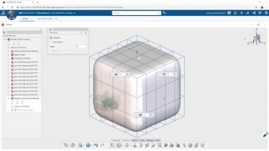
SOLIDWORKS Simulation Solutions
These failure modes on sucker rod connections and column-to-sheath connections increase costs and lengthen development times. To avoid these problems, it is necessary to use software that allows you to test different design options and evaluate product performance. These software must be simple and intuitive and offer continuous support.
Key Features of the SOLIDWORKS Platform
The solution to fatigue failure in sucker rods was to redesign the connection using stress concentration factors to achieve the optimal design. The image below on the left shows the result of the classic API design (option 1) and a new modified API design (option 2). The new design only has a change in the angle to better distribute the stress field compared to the previous design. You can observe on the right a comparison of the stress coefficients. The classic design has the worst values (red curve) and the stress coefficient of the new design is clearly better (green curve).

Results for sucker rod
Regarding the threaded connection, the performance of the seal at the connection was evaluated, which allowed the designer to define the critical loads. The image below allows me to show you the sealing area (left) and the seal performance rating (right). I generally use three types of factors: 1) SF – joint strength; 2) SP – peak tightness; and 3) SL – joint length. These factors allowed me to assess the performance of the seal.

Results for the threaded connection
To summarize the study of these two cases, we can draw the following conclusions:
To learn more about SOLIDWORKS Simulation solutions, visit our page Simulation Solutions.